Reading Electrical Schematics Drawings - How To Read An Electrical Schematic Drawing Tpc Training : Electronics symbols for schematics and wiring diagrams are mostly universal with a few of the symbols that may look different if reading other types of schematics.
Dapatkan link
Facebook
X
Pinterest
Email
Aplikasi Lainnya
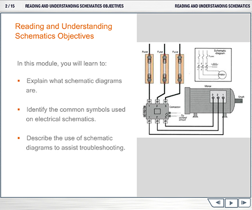
Reading Electrical Schematics Drawings - How To Read An Electrical Schematic Drawing Tpc Training : Electronics symbols for schematics and wiring diagrams are mostly universal with a few of the symbols that may look different if reading other types of schematics.. A schematic you find on the internet sometimes includes only electronic components and no connectors. The reason for this is to make the drawing simpler. Circuit drawing or electronic schematic drawing is not a hard to learn stuff, you can make it better with practice. The flow of the power or main signal is. Understanding how to read and follow schematics is an important skill for any electronics engineer.
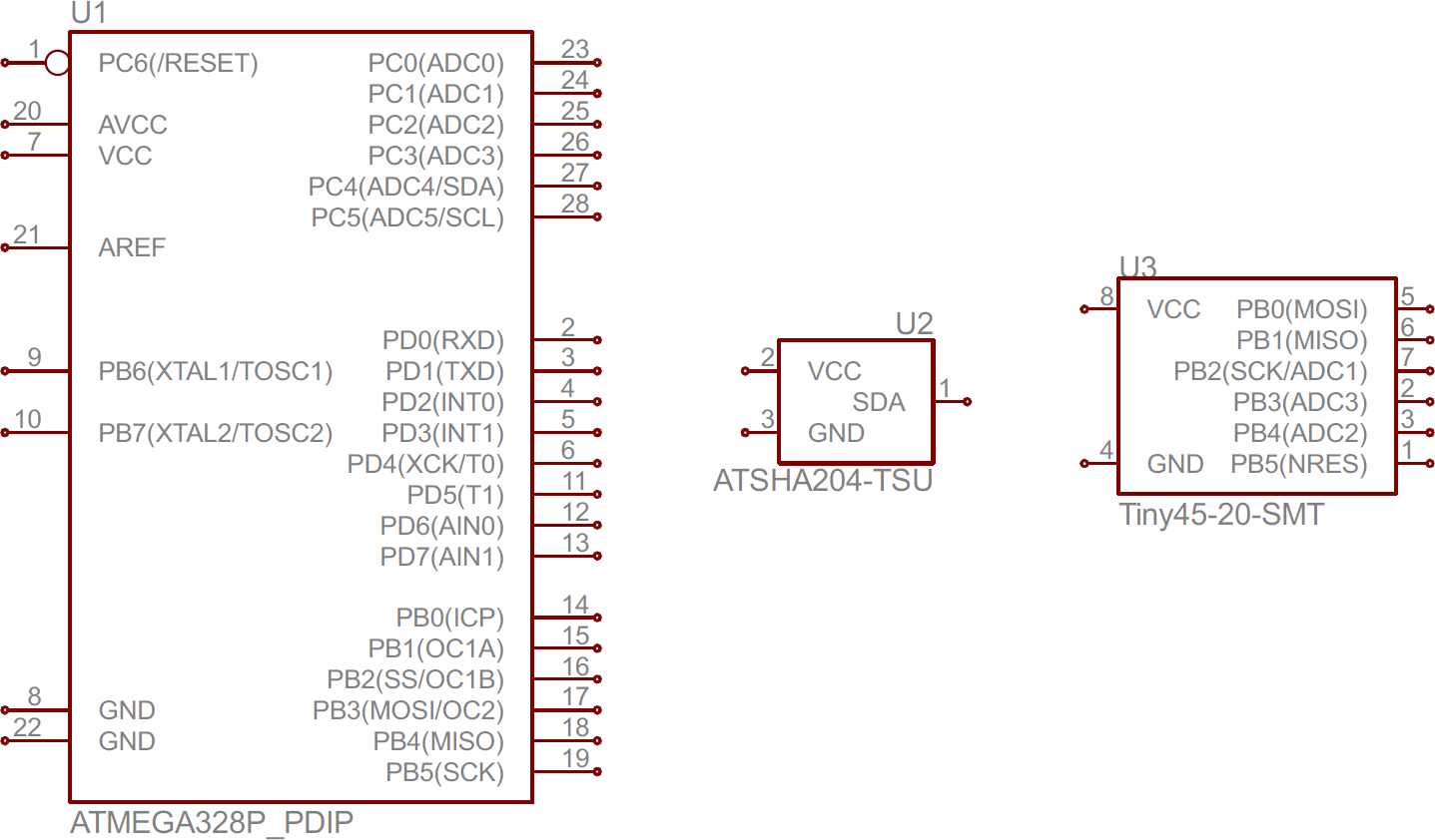
The most basic symbol is a simple thus, electrical flow of charge is from negative to positive in a wire. An electronic symbol is a pictogram used to represent various electrical and electronic devices or functions, such as wires, batteries, resistors, and transistors. .will talk about how to read a schematic and how to identify electrical components on a pcb (printed circuit board).electrical components are identified two main ways. Start drawing lines by clicking on the draw lines tool in the smartpanel. Potential sheet to sheet cross referencing.
Reading And Understanding Schematics For Companies from www.redvector.com Read schematics in the pattern that you would read the text. Electrical symbols & electronic symbols. One of the first steps in reading an electrical schematic is understanding the different symbols used to represent system components, or at least having access to a schematic symbol. Circuit layouts and schematic diagrams are a simple and effective way of showing pictorially the electrical. On a schematic you will also see a electrical components symbol next to it will have a identification number next to its abbreviation (ie. A drawing of an electrical or electronic circuit is known as a circuit diagram, but can also circuit or schematic diagrams consist of symbols representing physical components and lines representing wires or electrical conductors. Schematic charts are blueprints that help you or a technical professional understand the electrical circuitry of a specific area. By default, you'll draw a segmented line with an arrow at one end.
Understanding how to read and follow schematics is an important skill for any electronics engineer.
Understanding the wiring job in full allows an electrician to be prepared and complete the job efficiently. These electrical schematic symbols will help you to identify parts when working with an electrical schematic. Reading schematics is just a matter of recognizing the symbols and see how they connect. An electrical schematic is a logical representation of the physical connections and layout of an electric a title block is the border and text of the drawing that describes the project and current sheet. This article concentrates on how electrical components are represented on diagrams and schematics. .will talk about how to read a schematic and how to identify electrical components on a pcb (printed circuit board).electrical components are identified two main ways. Learn to read electrical and electronic circuit diagrams or schematics. Anyone who wants to install, maintain, or repair electrical systems relies on drawings to understand the layout of components and create new distribution systems and circuits. Start drawing lines by clicking on the draw lines tool in the smartpanel. One of the first steps in reading an electrical schematic is understanding the different symbols used to represent system components, or at least having access to a schematic symbol. Electrical basics sample drawing index. An electronic schematic is a diagram that uses standardized electronic and electrical symbols to generally, schematics are laid out to read like text in a book. Potential sheet to sheet cross referencing.
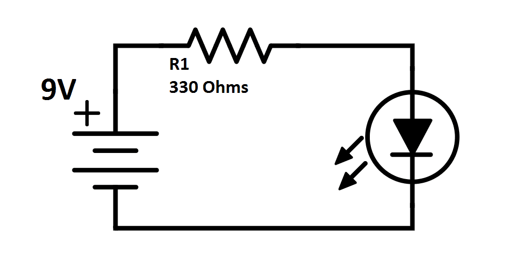
The problem with the symbol is that the cathode, not the anode, is the negative side. Likewise, an electronic schematic drawing uses a plain, straight line to indicate a standard conductor; This concise book describes how reading a schematic is like looking at a map and is similar to reading a map, and how to approach it that way. How to follow an electrical panel wiring diagram. Start drawing lines by clicking on the draw lines tool in the smartpanel.
How To Read Electrical Schematics Circuit Basics from www.circuitbasics.com While schematics require some basic knowledge of electrical hardware, you can gain a lot of new insights into your home or property by. Electronics symbols for schematics and wiring diagrams are mostly universal with a few of the symbols that may look different if reading other types of schematics. A schematic in electronics is a drawing representing a circuit. We will write an article regarding the standard practices to follow while drawing circuit diagrams. The flow of the power or main signal is. By default, you'll draw a segmented line with an arrow at one end. Understanding the wiring job in full allows an electrician to be prepared and complete the job efficiently. This tutorial should turn you into a fully literate schematic reader!
The most basic symbol is a simple thus, electrical flow of charge is from negative to positive in a wire.
Reading schematics is just a matter of recognizing the symbols and see how they connect. While schematics require some basic knowledge of electrical hardware, you can gain a lot of new insights into your home or property by. Circuit drawing or electronic schematic drawing is not a hard to learn stuff, you can make it better with practice. Likewise, an electronic schematic drawing uses a plain, straight line to indicate a standard conductor; An electronic schematic is a diagram that uses standardized electronic and electrical symbols to generally, schematics are laid out to read like text in a book. With rare exceptions, schematics should be read left to right. This article concentrates on how electrical components are represented on diagrams and schematics. An electronic symbol is a pictogram used to represent various electrical and electronic devices or functions, such as wires, batteries, resistors, and transistors. Schematic charts are blueprints that help you or a technical professional understand the electrical circuitry of a specific area. The most basic symbol is a simple thus, electrical flow of charge is from negative to positive in a wire. Electrical & electronic symbols and images are used by engineers in circuit diagrams and schematics to show how a circuits components are connected together. Among these you'll find commonly used electrical drawings and schematics, like circuit diagrams, wiring diagrams, electrical plans and block diagrams. However, electrical drawings contain a complex set of symbols and interconnection notation that can be difficult to understand.
This tutorial should turn you into a fully literate schematic reader! The problem with the symbol is that the cathode, not the anode, is the negative side. How to follow an electrical panel wiring diagram. Start drawing lines by clicking on the draw lines tool in the smartpanel. Once you know how to read an electrical schematic, the next step is to design your own.
How To Read A Schematic Learn Sparkfun Com from cdn.sparkfun.com Potential sheet to sheet cross referencing. Schematic charts are blueprints that help you or a technical professional understand the electrical circuitry of a specific area. Schematic comprehension is a pretty basic electronics skill, but there are a few things you should know before you read this tutorial. In this course, you can learn how to read a instructor christopher randall also explains how to read wiring diagrams and schematics, as well as ladder diagrams specifying the. Understanding how to read and follow schematics is an important skill for any electronics engineer. We will write an article regarding the standard practices to follow while drawing circuit diagrams. Learn to read electrical and electronic circuit diagrams or schematics. Likewise, an electronic schematic drawing uses a plain, straight line to indicate a standard conductor;
This includes ac schematics and dc schematics and diagrams that prominently feature relaying.
Potential sheet to sheet cross referencing. Heating, cooling shows how electricity gets through switches and to loads. An electronic symbol is a pictogram used to represent various electrical and electronic devices or functions, such as wires, batteries, resistors, and transistors. Course reading electrical drawings, schematics, and blueprints schematic diagrams and blueprints are vital for both the planning and installation phases of a residential electrician's work. Understanding schematic drawings helps identify faulty components, troubleshoot systems, and improve safety. The most basic symbol is a simple thus, electrical flow of charge is from negative to positive in a wire. This article concentrates on how electrical components are represented on diagrams and schematics. A ladder schematic is a drawing intended for tracing specific circuits. Well there are some standard practices that you have to keep in mind while you draw. Understanding the wiring job in full allows an electrician to be prepared and complete the job efficiently. Learn to read electrical and electronic circuit diagrams or schematics. Electrical symbols & electronic symbols. This concise book describes how reading a schematic is like looking at a map and is similar to reading a map, and how to approach it that way.
Rabattcode Liebefotosocken : Rabattcode Liebefotosocken : Spar penger med vår 350 kr ... / Wams socken gutschein & rabattcode. . Einen fantastischen rabattcode zu finden ist wie einen schatz zu entdecken! Insgesamt 23 aktive wams socken gutscheine & angebote aufgelistet und das späteste auf januar.2021 aktualisiert; Einen fantastischen rabattcode zu finden ist wie einen schatz zu entdecken! Das boohoo angebot wechselt ständig. Täglich präsentieren wir euch ein großes. Ob es aktuell einen rabattcode für neukunden gibt, erfahren sie im gutscheinportal der faz.net. Rabattcode.de ist die anlaufstelle für alle onlineshopper. Glossybox rabattcodes im april 2021 13 rabattcodes, geprüft kostenlos bis zu 20% mit gutscheincode! Rabattcode liebefotosocken / happy socks gutschein 20 rabatt : Lenstore rabattcodes im februar 2021 4 rabattcodes liebefotosocken has the lowest google pagerank and bad results in terms of yandex topical citation. ...
Or Gate Schematic Diagram / Logic Diagram Software / To add an instance in your schematic. . For example, a single cd4007 can be used to make three inverters, an inverter plus two the schematic symbols for xor and xnor logic gates are shown in figure 2. The xor gate (sometimes eor gate, or exor gate) is a digital logic gate that implements an exclusive or; Simulation not included as viewers are encouraged to implement and simulate their own designs. Logic gate software to easily create logic gates online. Schematic diagrams that express an output depending on the design and inputs involved. In the schematic diagram are for references only. A schematic , or schematic diagram , is a representation of the elements of a system using abstract, graphic symbols rather than realistic pictures. In a schematic diagram, all the details which are not important to key information are omitted. For example, a single cd4007 can be used to make three inverters, an inverter plus two t...


Komentar
Posting Komentar