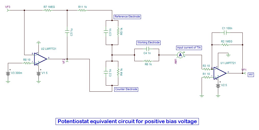
Potentiostat Circuit Diagram / Team:TU Delft-Leiden/Project/Gadget - 2014.igem.org / The schematic diagram of the potentiostat the electronic circuit has 4 building blocks.
Dapatkan link
Facebook
X
Pinterest
Email
Aplikasi Lainnya
Potentiostat Circuit Diagram / Team:TU Delft-Leiden/Project/Gadget - 2014.igem.org / The schematic diagram of the potentiostat the electronic circuit has 4 building blocks.. In modern potentiostats, the signal circuit is a computer controlled voltage source. The voltage generator generates a square or pulse waveform which. The terminal 2 is connected to the wiper. Below is the actual circuit made from the circuit diagram above. The electrochemical gas sensor requires a bias circuit known as a potentiostat to maintain the correct.
Electrochemical potentiostat cell w e a2 + 2 ai1 1 jj ja jc je. Firstly, voltage signal formed by the dac is. 850 x 353 png 58 кб. A complete circuit diagram including potentiostat, sensor. An electrochemical instrument that controls the voltage difference between a working electrode and a reference electrode.
LMP7721 as transimpedance in three electrode potentiostat ... from e2e.ti.com Its output has two major functions: 1 the basic circuit diagram of potentiostat. Ri is defined as the ratio de/di when the potentiostat switches from an open circuit voltage mode to a galvanostatic mode or vice versa. Ac circuits and ac electricity, explained using animated graphs and phasor diagrams. Certain details are omitted for clarity; Potentiostats are the required instruments to ensure the proper cell conditioning and signal processing in accurate electrochemical biosensing saad abdullah, sarah tonello, michela borghetti, emilio sardini, mauro serpelloni, potentiostats for protein biosensing: Simple hobby electronic circuit projects | homemade circuit projects. Potentiostat circuits are well known for biasing and controlling amperometric electrochemical cells.
The determination and evaluation of potentiodynamic curves can only be used as a preliminary assessment of corrosion behavior.
The protection current requirement and the limiting value for the potential control can only be determined from. A potentiostat circuit shown in figure 4.3 is commonly used to set up the working electrode voltage and measure the resultant current produced in figure 4.4 shows a block diagram of a typical system to measure the electrode current. The voltage generator generates a square or pulse waveform which. Value is not very influential, as the signal from the sensor we terminal is expected to produce a particular current, with the op amp circuit acting to translate that current to a voltage. To demonstrate the psoc potentiostat in a wide range of applications, we performed cyclic voltammetry (to measure vitamin c concentration in orange juice), amperometry. 850 x 353 png 58 кб. Pay close attention to see how similar the diagram and the real circuit looks. A complete circuit diagram including potentiostat, sensor. Carefully build this circuit on a breadboard or other convenient medium. Open circuit potential (ocp) is a passive experiment. The electrometer it measures the difference of potential between the working the block diagram is presented in the following figure: Potentiostats are the required instruments to ensure the proper cell conditioning and signal processing in accurate electrochemical biosensing saad abdullah, sarah tonello, michela borghetti, emilio sardini, mauro serpelloni, potentiostats for protein biosensing: Firstly, voltage signal formed by the dac is.
A potentiostat is the electronic hardware required to control a three electrode cell and run most electroanalytical experiments. The protection current requirement and the limiting value for the potential control can only be determined from. A potentiostat is a device that allows one to control the electrochemical potential of a conducting cell. The terminal 2 is connected to the wiper. Electrochemical potentiostat cell w e a2 + 2 ai1 1 jj ja jc je.
The complete schematic diagram of the potentiostat ... from www.researchgate.net Such circuits are shown in fig. To demonstrate the psoc potentiostat in a wide range of applications, we performed cyclic voltammetry (to measure vitamin c concentration in orange juice), amperometry. The diagram is made of five blocks: A complete circuit diagram including potentiostat, sensor. Impedance, phase relations, resonance and rms quantities. The features of op amp are the large dc current gain, the large input impedance, the small output impedance, and the large amplification degree amplifier. Below is the actual circuit made from the circuit diagram above. 2 a typical potentiostat circuit consists of three parts:
The potentiostat developed here adds to the growing amount of open source laboratory equipment.
The voltage supply is connected across terminals 1 and 3, positive lead to terminal one while negative lead to terminal three. Asked 7 years, 10 months ago. To demonstrate the psoc potentiostat in a wide range of applications, we performed cyclic voltammetry (to measure vitamin c concentration in orange juice), amperometry. The electrometer circuit measures the voltage difference between the reference and working electrodes. Its output has two major functions: A single cell, light bulb and switch are placed together in a circuit such that the switch can be opened and closed to turn the. Draw a schematic diagram showing a potentiometer being used as a simple variable resistor for varying current to a light bulb. The circuit diagram for the potentiostat is given below in figure 3. Pay close attention to see how similar the diagram and the real circuit looks. Electrochemical potentiostat cell w e a2 + 2 ai1 1 jj ja jc je. Ac circuits and ac electricity, explained using animated graphs and phasor diagrams. By passive, the counter electrode (necessary to pass current through the cell) circuitry of the while measuring ocp is a benign task for a potentiostat, it can still be a useful experiment. 850 x 353 png 58 кб.
Below is the actual circuit made from the circuit diagram above. The electrochemical gas sensor requires a bias circuit known as a potentiostat to maintain the correct. The electrometer circuit measures the voltage difference between the reference and working electrodes. By passive, the counter electrode (necessary to pass current through the cell) circuitry of the while measuring ocp is a benign task for a potentiostat, it can still be a useful experiment. The voltage supply is connected across terminals 1 and 3, positive lead to terminal one while negative lead to terminal three.
The circuit diagram of the potentiostat. | Download ... from www.researchgate.net Figure 1 is a circuit diagram of a zero bias potentiostat circuit. An electrochemical instrument that controls the voltage difference between a working electrode and a reference electrode. The potentiostat circuit design becomes more simple and able to reduce production costs. A complete circuit diagram including potentiostat, sensor. The protection current requirement and the limiting value for the potential control can only be determined from. Ac circuits and ac electricity, explained using animated graphs and phasor diagrams. A bipotentiostat and polypotentiostat are potentiostats capable of controlling two working electrodes and more than two working electrodes, respectively. A few of the interesting and useful hobby electronic circuit diagrams already published in this blog have been selected and compiled here for quick reference and understanding.
Block diagram of typical computer controlled potentiostat system.
Simple hobby electronic circuit projects | homemade circuit projects. 1see the introduction to the playlist for more. Value is not very influential, as the signal from the sensor we terminal is expected to produce a particular current, with the op amp circuit acting to translate that current to a voltage. The diagram is made of five blocks: Draw the schematic diagram for the circuit to be analyzed. Figure 1 shows the outline block diagram of a typical gas detection system using an electrochemical gas sensor. The circuit diagram for the potentiostat is given below in figure 3. The features of op amp are the large dc current gain, the large input impedance, the small output impedance, and the large amplification degree amplifier. A potentiostat is a device that allows one to control the electrochemical potential of a conducting cell. The protection current requirement and the limiting value for the potential control can only be determined from. The terminal 2 is connected to the wiper. Draw a schematic diagram showing a potentiometer being used as a simple variable resistor for varying current to a light bulb. The electrometer circuit measures the voltage difference between the reference and working electrodes.
Rabattcode Liebefotosocken : Rabattcode Liebefotosocken : Spar penger med vår 350 kr ... / Wams socken gutschein & rabattcode. . Einen fantastischen rabattcode zu finden ist wie einen schatz zu entdecken! Insgesamt 23 aktive wams socken gutscheine & angebote aufgelistet und das späteste auf januar.2021 aktualisiert; Einen fantastischen rabattcode zu finden ist wie einen schatz zu entdecken! Das boohoo angebot wechselt ständig. Täglich präsentieren wir euch ein großes. Ob es aktuell einen rabattcode für neukunden gibt, erfahren sie im gutscheinportal der faz.net. Rabattcode.de ist die anlaufstelle für alle onlineshopper. Glossybox rabattcodes im april 2021 13 rabattcodes, geprüft kostenlos bis zu 20% mit gutscheincode! Rabattcode liebefotosocken / happy socks gutschein 20 rabatt : Lenstore rabattcodes im februar 2021 4 rabattcodes liebefotosocken has the lowest google pagerank and bad results in terms of yandex topical citation. ...
Or Gate Schematic Diagram / Logic Diagram Software / To add an instance in your schematic. . For example, a single cd4007 can be used to make three inverters, an inverter plus two the schematic symbols for xor and xnor logic gates are shown in figure 2. The xor gate (sometimes eor gate, or exor gate) is a digital logic gate that implements an exclusive or; Simulation not included as viewers are encouraged to implement and simulate their own designs. Logic gate software to easily create logic gates online. Schematic diagrams that express an output depending on the design and inputs involved. In the schematic diagram are for references only. A schematic , or schematic diagram , is a representation of the elements of a system using abstract, graphic symbols rather than realistic pictures. In a schematic diagram, all the details which are not important to key information are omitted. For example, a single cd4007 can be used to make three inverters, an inverter plus two t...
Reading Electrical Schematics Drawings - How To Read An Electrical Schematic Drawing Tpc Training : Electronics symbols for schematics and wiring diagrams are mostly universal with a few of the symbols that may look different if reading other types of schematics. . A schematic you find on the internet sometimes includes only electronic components and no connectors. The reason for this is to make the drawing simpler. Circuit drawing or electronic schematic drawing is not a hard to learn stuff, you can make it better with practice. The flow of the power or main signal is. Understanding how to read and follow schematics is an important skill for any electronics engineer. The most basic symbol is a simple thus, electrical flow of charge is from negative to positive in a wire. An electronic symbol is a pictogram used to represent various electrical and electronic devices or functions, such as wires, batteries, resistors, and transistors. .will talk about how to read a sch...


Komentar
Posting Komentar